Adding a Harley
Style Ignition Switch
|
Replace your OEM
ignition with the rider friendly HD flip top switch!
|
|
Sometimes Motorcycle Design Engineers like to have a little fun and
locate the ignition switches in hard to reach places, just so they can
snicker when you fall over reaching for the keys, or they place
ignitions so close to body parts that your keys will damage the finish
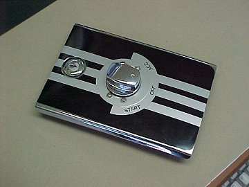
on your gorgeous bikes. For years some of the larger Harley bikes have
incorporated a flip top style switch and located it on the top of the
console or fuel tank for easy, instant access. These switches do not
require the use of an ignition key to operate, but they have a hidden
ignition lock underneath the flip up top cover, so you can LOCK your
ignition when away from the bike. This design not only carries a clean,
custom look, but it keeps dirt and water out of the key slot to reduce
corrosion problems.
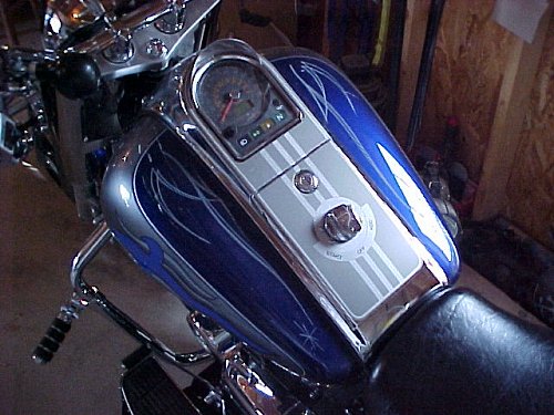
The LC Intruder has a perfect location for the adaptation of an HD
style switch, right in the fuel door! Now, before you go thinking "Kaboom!"
and having visions of mushroom clouds, consider the fact that the LC
vents its fuel tank up under the air box covers via a carbon canister,
well away from the fuel door area. The fuel cap is only inward vented
and vapors cannot escape into the fuel door area once the cap is on.
Also consider that there are no exposed contact points on the new
ignition switch to cause a spark, and if that ain't enough to ease your
concern, you can always silicone seal the underside of the switch once
its installed.
Of course, this is no guarantee that there may not possibly be a
threat of danger involved, and I encourage you to proceed at your own
risk. To date, I have never heard of any problems with this
modification, but that doesn't mean there haven't been any. ;-) Do it if
it feels good, but do it at your own risk.
|
Click the Photos for Larger Format |
1. Remove the seat by taking the two front bolts, and the two back
allen head bolts off, there by exposing the wire connector we will be
dealing with. Then remove the fuel door by unlocking it and removing the
two phillips head screws.
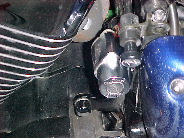
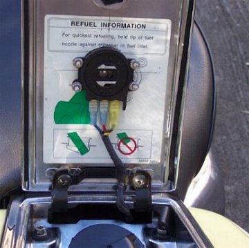
2. Locate, on the left side of the fuel filler tube, the ignition switch
wires it is a small square connector with 5 wires protruding from either
side. The color of the wires are Red, Orange, Orange with a
Yellow tracer, Gray, and Brown.
|
 |
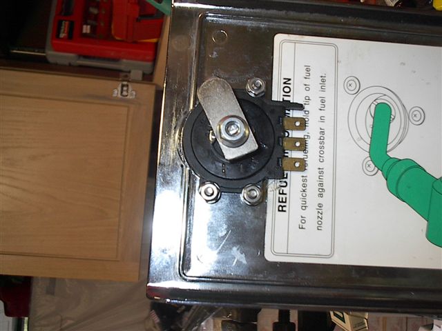
Remove the
original switch by removing the one allen
head screw located on top of the switch
and removing by pulling, carefully by the switch.
3. Once the switch is removed, cut all 5 wires about half way between
the switch and the connector, discard the old switch. The Gray and Brown
wires are your running and tail lights, the lights are wired on a loop and don't need to
be connected to the Ignition, but most models will require that they be
at least connected to each other for this mod, so strip a bit of
insulation off and twist these two wire ends together and tape
them up. Now your done with two of the 5
wires.
Note! Most later
model bikes require that the grey and brown wires be connected
to each other. Before you finish the
project, check all running lights and tail lights for operation.
If they aren't working, you may need to tap the brown and/or
grey wire to a power source, such as the orange wire from the
ignition switch.
|

|
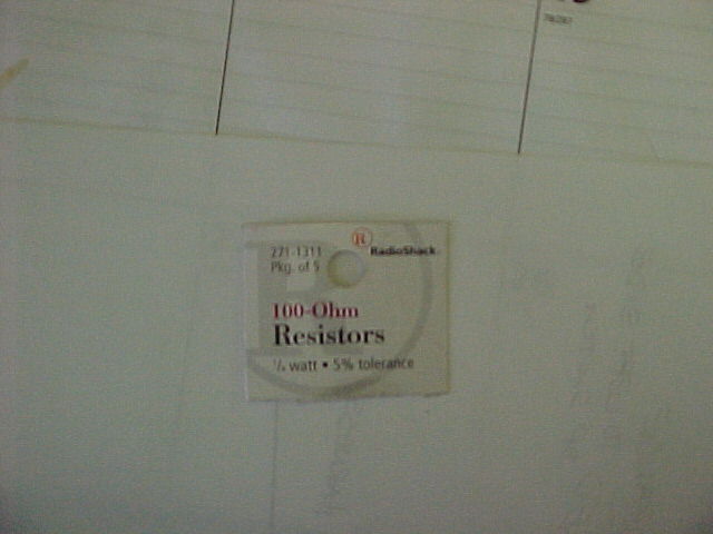
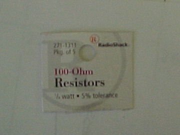
4. Now were
going to start wiring. At this point you will need a Resistor,
available from Radio Shack, part # 271-1311, 100-ohm, 1/4 watt
5% tolerance.
|
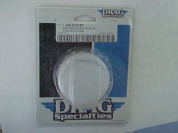
And the heart of this operation, a Harley type switch.
I used a Drag Specialties part # DS-272187, Side Hinge Ignition Switch 93-00.
Cost about $30.00 including shipping.
|
|
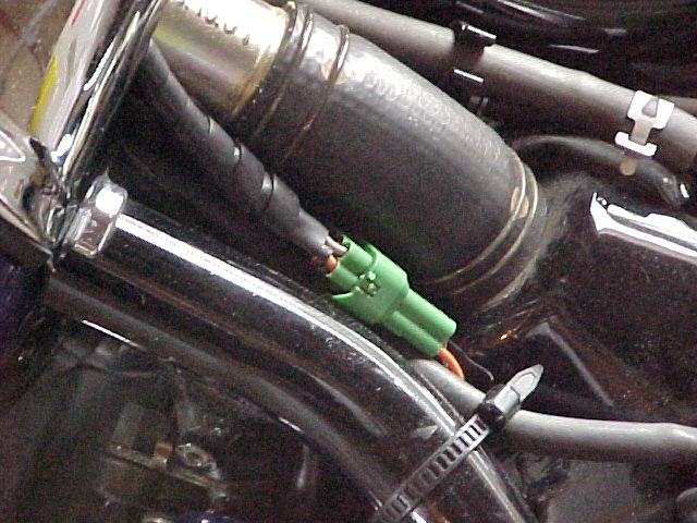
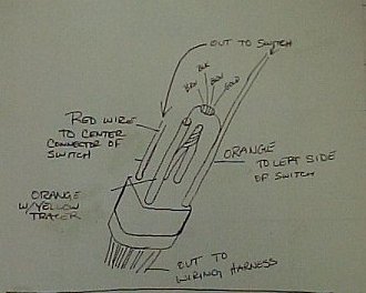
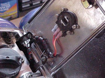
Strip back the insulation on the Red, Orange, and Orange W/ Yellow
Tracer wires. Solder a resistor from the Orange w/Yellow to the Orange
wire, connect a 10" section of 16ga. wire to the red wire and a 10"
section to the Orange wire, and attach a connector at the end of each to
attach to the new switch
set the new wire connector to the side.
(The two wires in the background are your grey
and brown wires)
|
 |
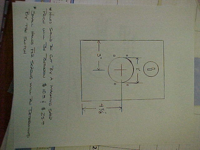
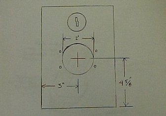
| 5. At this time the fuel door will need to be drilled to accept the new
switch.
Anyone with a good drill press could be able to accomplish this, but be
advised, a new fuel door without the lock mechanism is $180.00. I chose
to allow a machine shop to drill mine, it cost me $20.00, I think well
worth it. If you go this route take the new switch with you so it can be
aligned properly. |
 |
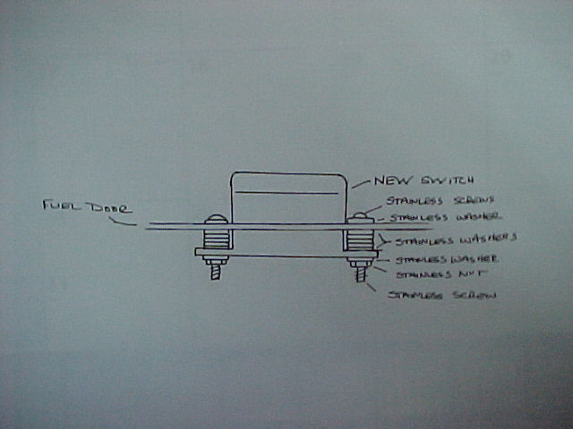
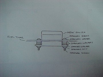
6. Now that the holes are drilled it would be a good time to decorate,
the door with the on/off/access decals if you so desire. After this is
done, attach the new switch using the SS screws, washers and bolts. The
connectors needed a little clearance so I shimmed them with 5 washers.
Cut the excess screw length off flush with the
nuts with a Dremell tool.
I did leave out, in the pic, the lock washer under the nut and the
thread glue. I also ran a bead of silicon around the outside of the
switch for waterproofing.
|
|
You can use Auto Grade "Blackout Tape" to add design
character to the fuel door, to further enhance the project.
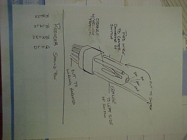
7. Re-attach the fuel door, attach the new wiring to the connector on
the wiring harness side. Run the wires under the fuel door, connect the
Red one to the center prong, the orange one to left prong, and cover the
right prong with a spare connector
I'm going to use this leftover connection later for a cigarette lighter.
|
|
8. Close the fuel door, re-attach the seat and try the new switch out.
|
|
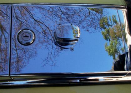
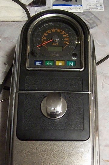
"Rasoul"
used flush mounted flat head screws for a clean, smooth topside
appearance. (Below)
|

|
|
|
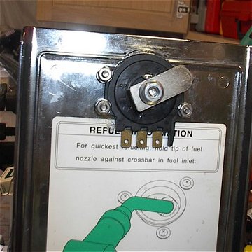
Dick "Reno" took his switch project a
little further by moving it upward on the panel and adding a
fuel door lock catch to the switch post. Now the switch does
double duty! (Below) |
If you're interested in taking on a bit of metalworking to
achieve the double duty latch/switch function,
CLICK HERE to download Rasoul's follow-up PDF file of
the latch conversion process.
|
 |
Materials Needed
|
Tools needed
|
1. 1 ft of 16ga. red wire
2. 1 ft of 16ga. orange wire
3. 2 16ga. inline connectors
4. 3 Quick disconnects
5. 28 #8 SS washers
6. 4 #8 SS internal tooth washers
7. 4 SS 8x24x1" machine screws
8. 4 SS 8x24 nuts
9. clear Silicon
10.1 Side Hinge Ig switch, Drag Specialties #DS 272187
11.Electric tape or shrink tubing
12.1 package of Resistors, Radio Shack #271-1311
13.Locktite
|
1. Wire cutters
2. 5&6 mm allen wrenches
3. Blade screw driver
4. Soldering iron & electrical grade solder
5. 10mm socket & ratchet
6. 8mm end wrench
7. Dremmel tool w/ a grinding wheel or a Hack saw to cut off the machine
screws
|
Many thanks to my cyber
friends Ronnie Cline, for the excellent How-To write-up and
photos,
and to "Rasoul" and "Reno" for the additional option photos for
this project!!
|
|