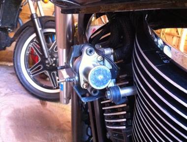
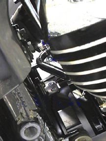
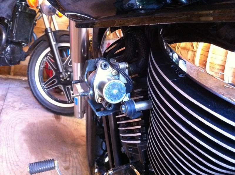
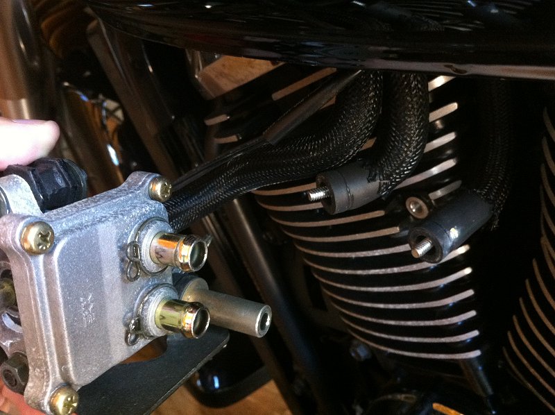
| Looking at it from the rear of the bike, you can see the
wiring that runs to the solenoid, and the two Phillips head screws that hold
the solenoid to the valve body. |
 |
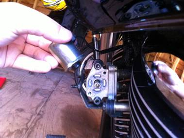
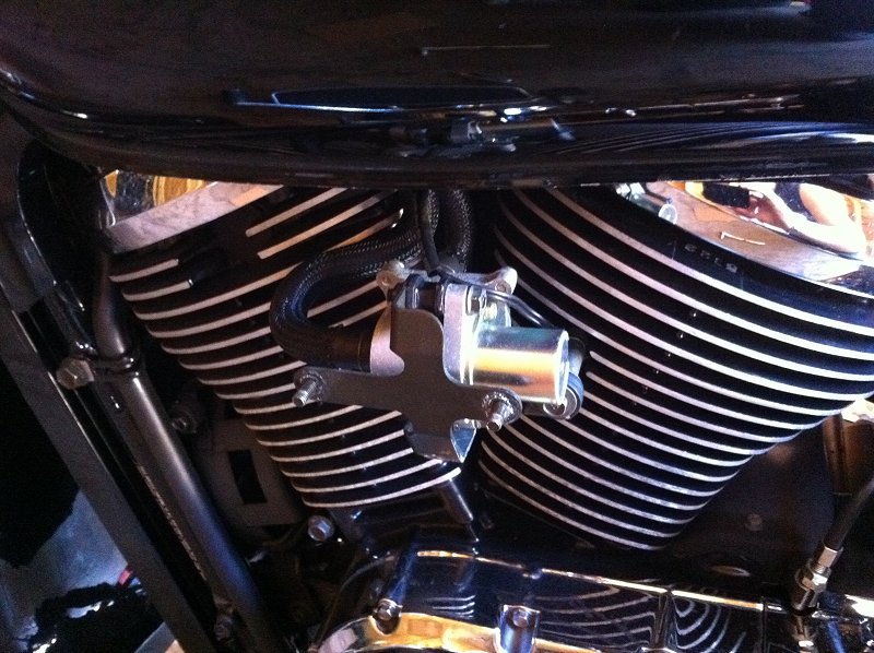
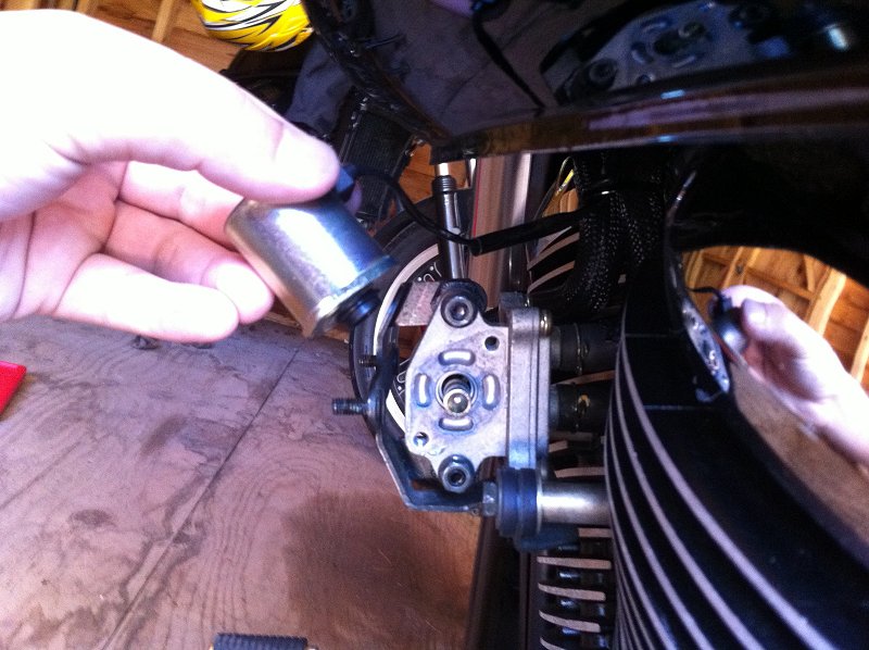
| Remove the solenoid (shown here being held) from the valve
body and hang it off to the side while the remainder of the system is
removed. The solenoid must be retained and connected to the bike's
harness connector to avoid engine fault codes during startup. Use the
two supplied plastic zip ties to secure it up out of site, under the tank. This can be done by looping the zip ties over the main wiring harness
and through the solenoid screw holes, then cinch them up to the main
harness or to the bike's framework.. You may find it easier and more
secure to relocate the solenoid behind the right side neck cover (with the
ignition switch). Thanks to Bob Warren for that tip! |
 |
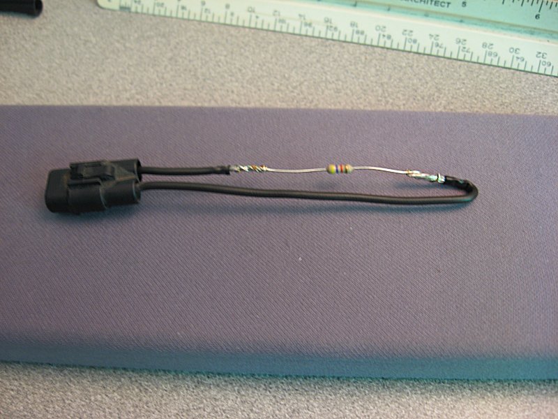
NOTE:
An alternative to retention of the solenoid is replacing it with a 4.7k-Ohm
1/4 Watt inline resistor. You can learn more about that
HERE. |
 |
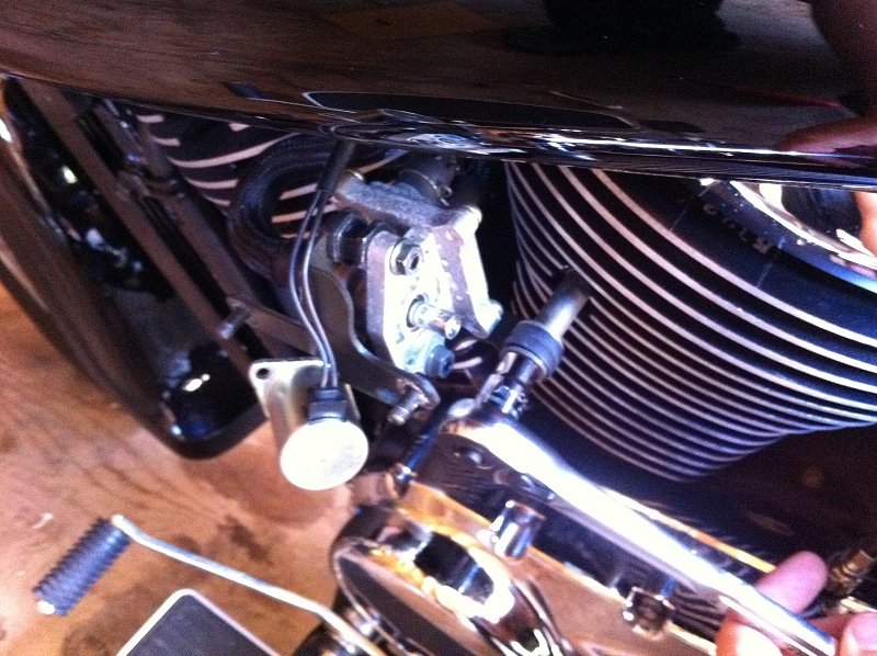
| Remove the valve assembly and bracket by removing the two
bolts that attach it to the cylinder casings. Your kit will come with small
filler bolts to put back in the attachment holes. |
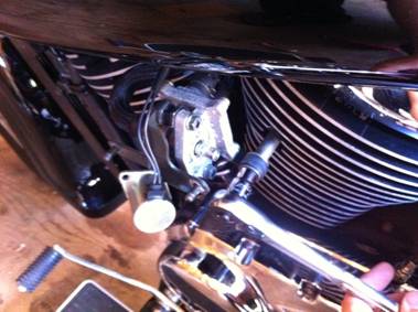 |
| With the valve and bracket assembly loose, you can now
access the two air delivery tubes on the backside. |
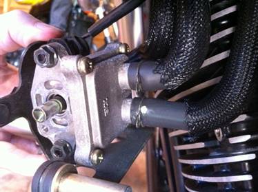 |
| If you simply wish to block, but not remove the system, you
can insert a pair of round head (phillips or allen) screws headfirst into
the rubber tubing. The tubing can then be replaced onto the valve nipples
for reassembly, and the screws are easily removed later with a pair of
needle nose pliers. For complete system removal, continue to Step 2. |
 |
| STEP 2. REMOVE
THE AIR BREATHER ASSEMBLY. |
| Remove the two Allen screws on the
air breather cover and remove air filter. |
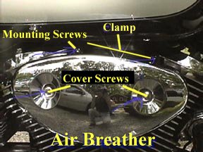 |
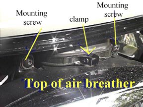
Remove two Allen screws from the case on the top.
Loosen the hose clamp on the top of the air breather body with
the #2 screwdriver. |
 |
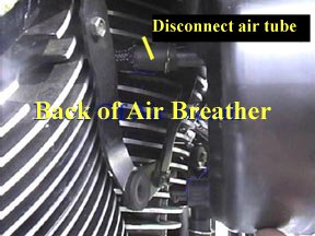
| Pull out and down on the body and the hose will come with it. (be
careful with it, it is tight, but it will come out) |
| Remove hose from back of air breather body and put the large cap
from the kit on the port . Then use the clamp from the original
hose to secure it to the port. |
 |
LEAVE THE AIR BREATHER OFF FOR NOW, AS YOU WILL NEED THE
ROOM
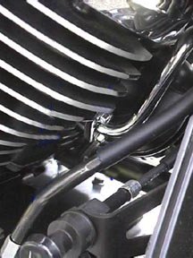
| STEP 3. REMOVE
THE REAR AIR DELIVERY TUBE |
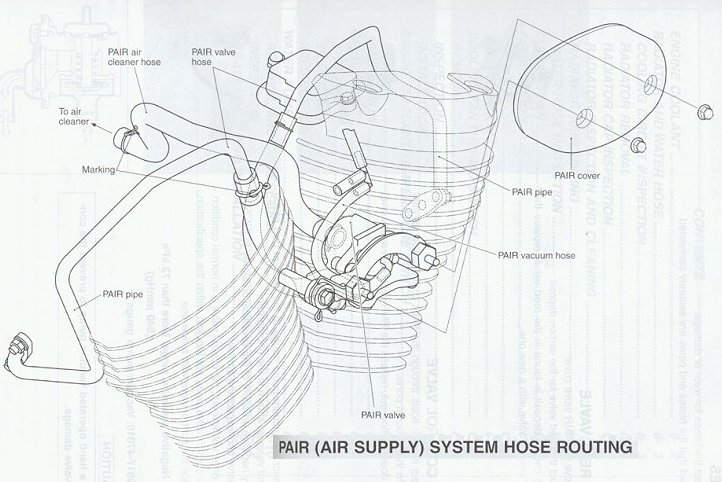
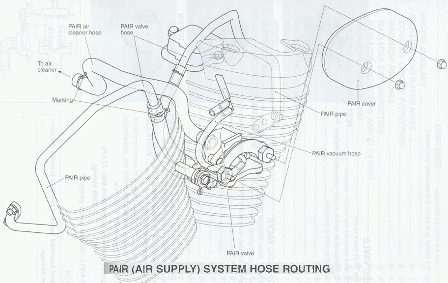
After removing the rubber tubes from the top of both chromed
air tubes (see diagram at top of page),
Loosen the two chrome bolts with 8mm box wrench
and remove the bolts.
The chrome air delivery tube and flange will feed out the left side of the bike.
It does not come out straight so turn it and
twist it as it comes out . It takes some firmness , but not brute
force.
Apply small amount gasket sealer around hole.
Apply small amount of gasket sealer to gasket and adhere to cover
plate (from the kit).
Apply small amount of gasket sealer to chrome bolt threads and
start the bolts in the holes.
Tighten as far as possible with fingers and use box wrench to
finish up. |
 |
| STEP 4. MAKE ROOM
FOR REMOVAL OF THE FRONT TUBE |
The next steps are recommended to get the room
needed to work, especially for people with average to large hands.
Remove the two Allen head bolts that hold the exhaust to the head
and move the pipe out of the way.
Remove the 12 mm bolt that holds the horn bracket to the frame.
Remove the radiator cover by pulling out from the bottom and
lifting off the tabs at top
Remove the three 10 mm bolts that hold it on. Two at top, one at
bottom.
Remove the three 10 mm bolts from the cooling fan and push it
down a little.
| STEP 5. REMOVE
THE FRONT AIR DELIVERY TUBE |
With the box wrench loosen the two 8mm chrome
bolts as far as possible
Now squeeze your hand between the frame and the radiator and put
the 8mm nut driver tip on the chrome bolts and take them out.
Remove the air delivery tube (same twisting and turning as the
rear).
Repeat the gasket sealer steps for the back flange.
Put the chrome bolts back in and tighten them by hand as far as
you can and use the box wrench to finish it up. |
 |
Put the 12 mm bolt back in for the horn and tighten up.
Put the two 10 mm bolts back in the cooling fan and tighten up.
Put the three 10 mm bolts back in the radiator and tighten up.
Put the radiator cover back on (top first).
| STEP 6. RE-INSTALL
THE AIR BREATHER |
Simply reverse the procedure outlined above.
STEP
7.
TAKE PICTURES AND SHOW ALL YOUR FRIENDS!!
|
|
