Pair
Valve Removal Made Easy
|
| by "Moccasin" Mike |
| ********************************************************* |
For the
Volusia 800
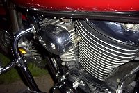
Click to see a full screen view of GaryM's
Gorgeous "De-Paired" Volusia
Recommended Tools
8mm Box Wrench (the longer the better) / 10 mm Socket and Wrench
/ 12 mm Combination Wrench
Long #2 Phillips Head Screwdriver / Gasket Sealer / Lots of
Patience
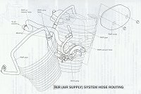
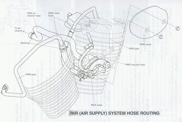
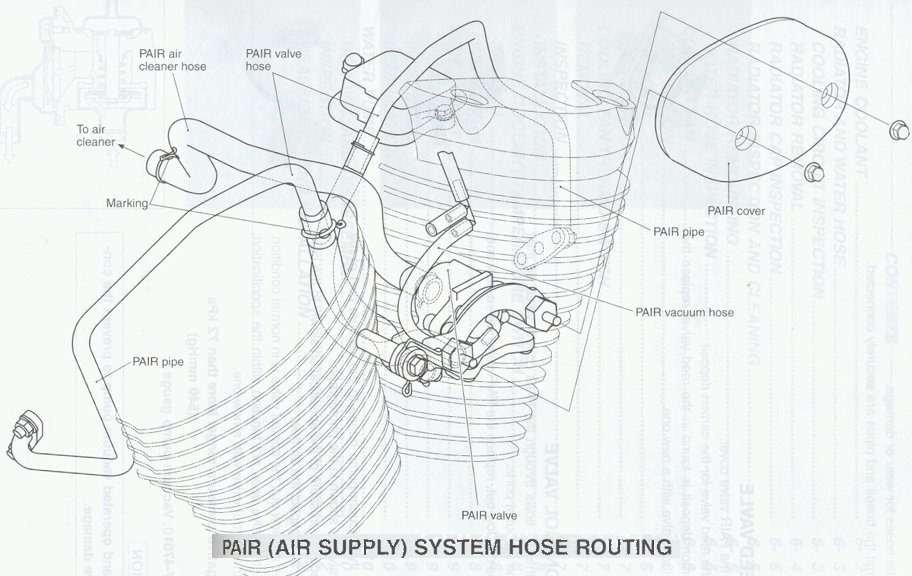
Click here to see a Service Manual diagram of the
complete Volusia Pair System,
for a visual reference to the following instructions.
NOTE** If you are using a removal kit by "Moccasin"
Mike, be aware that these kits are packaged to be used
universally on the LC, Marauder and Volusia. YOU WILL
HAVE KIT COMPONENTS LEFT OVER!
All metal components of the removal kits have been "Blackened"
with satin finish engine paint, and baked at 400 degrees to match
your engine block. Some damage to paint may occur during shipping
and/or installation.
YOU HAVE OPTIONS!!
There are
three viable options for disabling and/or removing the Volusia
Pair Valve System, graduating from a simple disable without
removal of components (best if you are concerned about warranty
issues) to valve only removal, to the complete removal of the
entire system.
OPTION
1: Simple Disable
Read and follow Step 1 of
the Complete Removal instructions below, except that you
do not need to remove or eliminate the threeway vacuum
connector. Just leave it as is. |
OPTION
2: Partial Removal (Valve assembly and housing only)
Read and follow Steps 1
and 2 of the Complete removal instructions below.
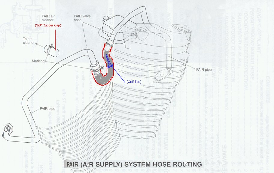
Then remove the rubber connecting hose from the rear
metal air delivery tube (pair tube).
Plug the remaining (front) rubber connecting hose with a
golf tee or small round head bolt,
then connect it to the rear metal air tube and secure it
with the hose clamp.
then re-install the air breather assembly after capping
the rear port.
Click here to see a modified
Service Manual diagram showing the "bridged"
air tubes.
This option requires only a golf tee (or small round head bolt), a 3/8" rubber
vacuum cap, and a pair of short 6mm bolts to fill the
pair assembly mounting holes left in the cylinder walls (for
better appearance).
The vacuum cap and screws are available at your local
auto store. (No kit purchase is necessary) |
OPTION
3: Complete System Removal
(Instructions
Below)
This option will allow you to completely remove
the valve assembly and air delivery tubes for an even
cleaner appearance, but requires building or purchasing a
set of blocking plates and gaskets for the air tube
flanges at the exhaust ports.
If you would like to purchase a complete removal kit from
"Moccasin" Mike, the kits are $21.00 U.S. and
include worldwide ground shipping costs. E-mail me
("Snake Mail" link at bottom of the page) for
purchase instructions. |
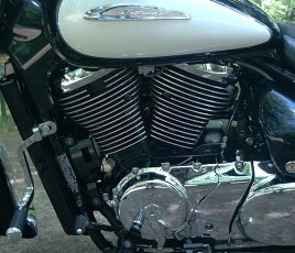
| STEP 1. REMOVE
THE COVER AND PAIR VALVE ASSEMBLY (Click the
photos for larger views) |
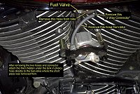
| Remove the two 8mm hex nuts from the pair valve
cover. |
 |
| Take out the two 10 mm bolts from valve body that hold it to the
jugs. |
 |
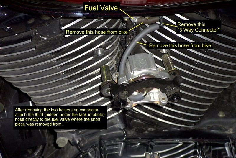
| Pull the vacuum tubes off the three-way connector and connect the
one from the engine to the fuel valve on bottom of tank,
eliminating the three-way connector. |
 |
| Slide the 3 ring clamps up the hoses on the back of the valve,
and remove the valve assembly, then the ring clamps. |
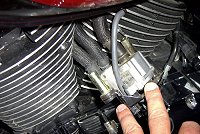 |
Install any two of the black painted stainless steel bolts from
the kit into the holes that are on the side of the jugs if you
are not keeping the cover there for looks.
If you only wish to disable the pair valve, but not remove any of
it's components, insert a golf tee or round head screw head first into each of the
two lower rubber tubing (Pair Tube) pieces. Leave a small portion of the
pointed end of the tee sticking out of the end of the rubber tube
(for easy removal later if necessary), and re-install the rubber
tubing pieces to the pair valve, re-attach the valve and replace
the cover.
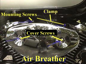
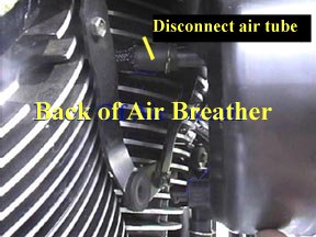
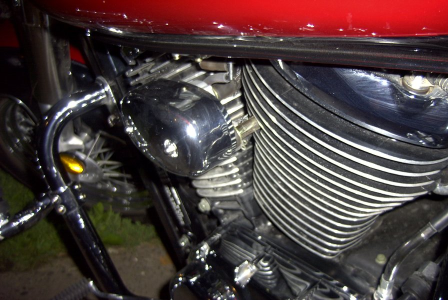
| STEP 2. REMOVE
THE AIR BREATHER ASSEMBLY. |
| Remove the two Allen screws on the
air breather cover and remove air filter. |
|
Remove two Allen screws from the case on the top.
Loosen the hose clamp on the top of the air breather body with
the #2 screwdriver. |
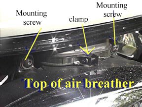 |
| Pull out and down on the body and the hose will come with it. (be
careful with it, it is tight, but it will come out) |
| Remove hose from back of air breather body and put the large cap
from the kit on the port . Then use the clamp from the original
hose to secure it to the port. |
|
LEAVE THE AIR BREATHER OFF FOR NOW, AS YOU WILL NEED THE
ROOM
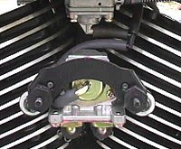
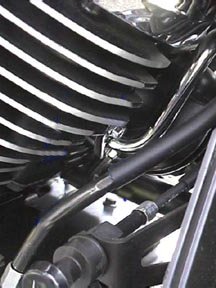
| STEP 3. REMOVE
THE REAR AIR DELIVERY TUBE |
After removing the rubber tubes from the top of both chromed
air tubes (see diagram at top of page),
Loosen the two chrome bolts with 8mm box wrench
and remove the bolts.
The chrome air delivery tube and flange will feed out the left side of the bike.
It does not come out straight so turn it and
twist it as it comes out . It takes some firmness , but not brute
force.
Apply small amount gasket sealer around hole.
Apply small amount of gasket sealer to gasket and adhere to cover
plate (from the kit).
Apply small amount of gasket sealer to chrome bolt threads and
start the bolts in the holes.
Tighten as far as possible with fingers and use box wrench to
finish up. |
|
| STEP 4. MAKE ROOM
FOR REMOVAL OF THE FRONT TUBE |
The next steps are recommended to get the room
needed to work, especially for people with average to large hands.
Remove the two Allen head bolts that hold the exhaust to the head
and move the pipe out of the way.
Remove the 12 mm bolt that holds the horn bracket to the frame.
Remove the radiator cover by pulling out from the bottom and
lifting off the tabs at top
Remove the three 10 mm bolts that hold it on. Two at top, one at
bottom.
Remove the three 10 mm bolts from the cooling fan and push it
down a little.
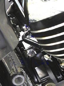
| STEP 5. REMOVE
THE FRONT AIR DELIVERY TUBE |
With the box wrench loosen the two 8mm chrome
bolts as far as possible
Now squeeze your hand between the frame and the radiator and put
the 8mm nut driver tip on the chrome bolts and take them out.
Remove the air delivery tube (same twisting and turning as the
rear).
Repeat the gasket sealer steps for the back flange.
Put the chrome bolts back in and tighten them by hand as far as
you can and use the box wrench to finish it up. |
|
Put the 12 mm bolt back in for the horn and tighten up.
Put the two 10 mm bolts back in the cooling fan and tighten up.
Put the three 10 mm bolts back in the radiator and tighten up.
Put the radiator cover back on (top first).
| STEP 6. RE-INSTALL
THE AIR BREATHER |
Simply reverse the procedure outlined above.
STEP
7.
TAKE PICTURES AND SHOW ALL YOUR FRIENDS!!
|
Many thanks to Gary
Margelony "Gary_M" and Derek Ryan "Beretta"
for their assistance in working up this information for the
Volusia.
Use your "Back" button or
Click HERE
to go back

